
Finished component reference · drawing-based production
Black Finned Aluminum Die Cast Electronics Enclosure
A finished black enclosure with cooling fins, front I/O openings and rear mounting interfaces. Fanless industrial computers, network devices or control electronics after thermal load, PCB layout, connectors and mounting are confirmed.
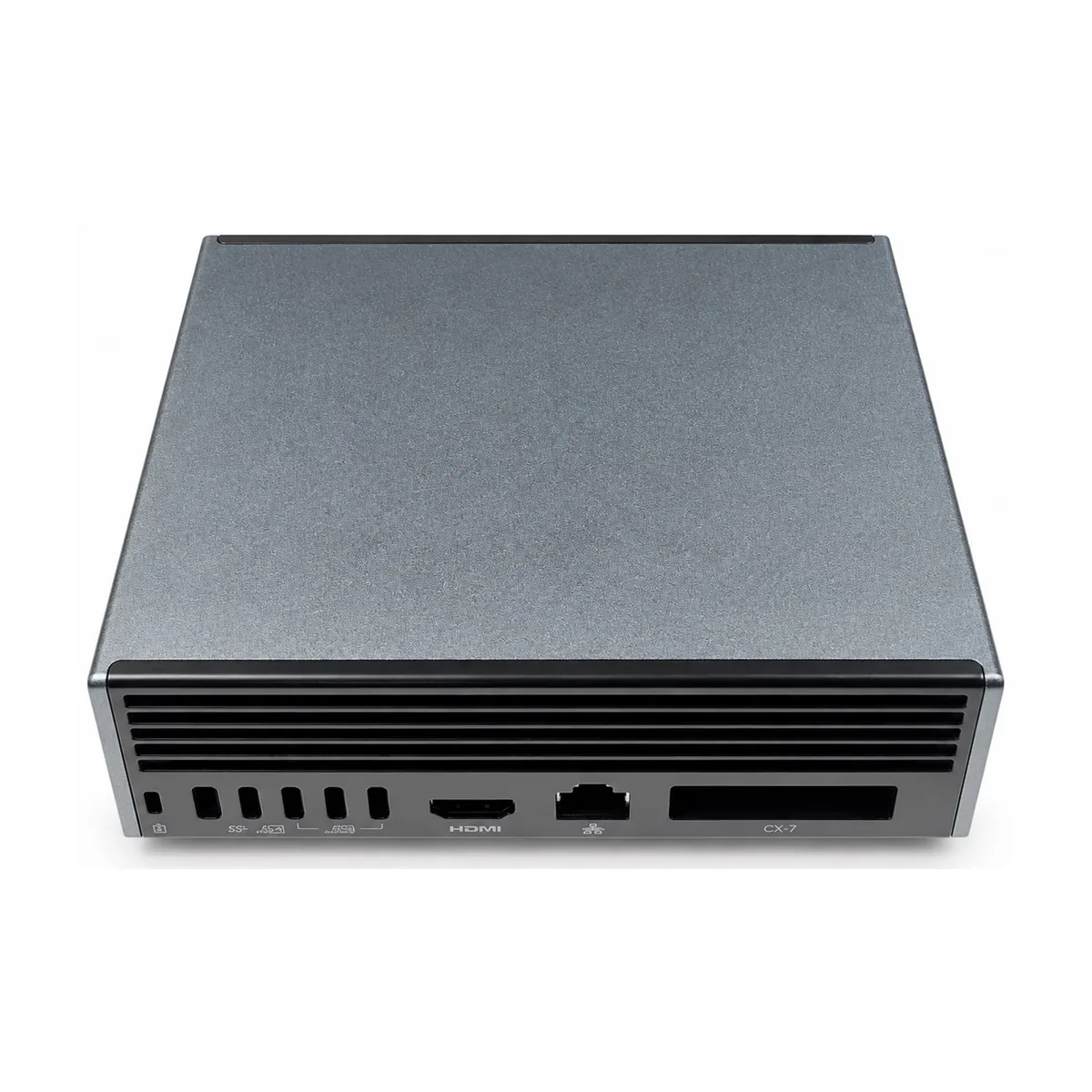 Aluminum alloy; exact grade confirmed by drawing and purchase specification
Photo-backed manufacturing evidence
Use the finished component as a reference, then control the new project from its drawing.
The photographs show a completed Huabo production example. They support discussion of comparable geometry, machining access and finish handling, but they do not define the alloy, dimensions, tolerances or performance limits for another project.
| Review area | What the photograph supports | What the current project must define |
|---|---|---|
| Finished-part evidence | A real completed component photographed after secondary operations | Current 3D model, controlled 2D drawing and revision |
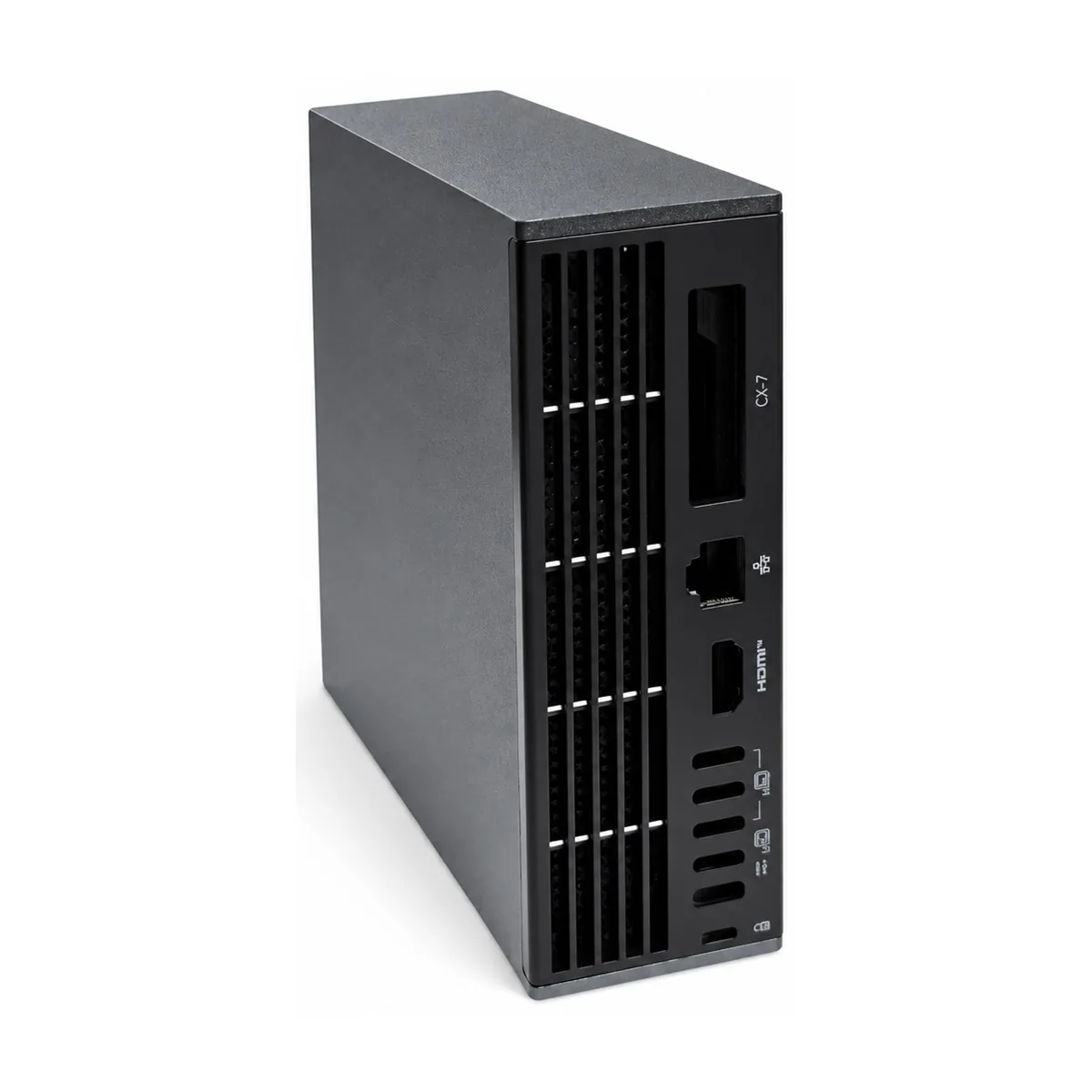
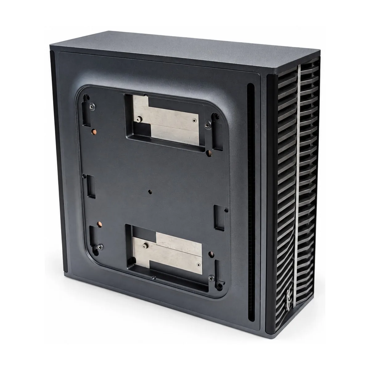
| Geometry | A compact rectangular enclosure combines dense side fins, front ventilation and connector openings, and a rear plate with defined mounting interfaces. | Envelope, wall sections, draft, datums and controlled features |
| Application context | Fanless industrial computers, network devices or control electronics after thermal load, PCB layout, connectors and mounting are confirmed. | Assembly function, loads, exposure, interfaces and regulatory needs |
| Material basis | Aluminum alloy; exact grade confirmed by drawing and purchase specification | Required alloy standard, material certificate and approved alternatives |
| Production scope | DFM, tooling, high-pressure die casting, trimming and required secondary operations | Annual volume, validation level, surface finish, packaging and delivery requirements |
| Critical control | Check finish colour and coverage, adhesion requirement, port location, enclosure flatness, fin damage, threaded features and any EMC or sealing interface. | Numeric acceptance limits, test method, sampling and report format |
Part-specific engineering review
The control plan follows the functional relationships visible in this geometry.
The points below are the practical issues to close during DFM, quotation and sample approval. The customer drawing remains the authority for every numeric limit.
Assembly role to confirm
Fanless industrial computers, network devices or control electronics after thermal load, PCB layout, connectors and mounting are confirmed.
Geometry and tooling focus
A compact rectangular enclosure combines dense side fins, front ventilation and connector openings, and a rear plate with defined mounting interfaces.
Machining and finish focus
Connector cutouts, threads, mating faces and masked zones must stay related through machining, cleaning and the approved black finish route.
Inspection and release evidence
Check finish colour and coverage, adhesion requirement, port location, enclosure flatness, fin damage, threaded features and any EMC or sealing interface.
Controlled production route
From drawing review to a repeatable finished component.
The final route is selected only after alloy, annual demand, tolerances, finish and validation requirements are known.
- Drawing and DFM reviewConfirm revision, functional datums, wall transitions, draft, parting, slides, machining stock and critical characteristics.
- Tooling and casting trialPlan filling, overflow, venting, cooling and ejection around functional and visible surfaces; record trial corrections before approval.
- Secondary operationsTrim, machine, deburr, clean and finish only to the controlled route, with fixtures transferring the agreed datum scheme.
- Inspection and releaseLink material records, first-piece results, appearance evidence and any functional test to the current drawing revision.
Finished product views
Multiple views of the same completed component.
These angles document the exterior finish, cooling features and mounting interfaces without implying stock dimensions or catalogue specifications.
2026 finished component
Front view
A finished black enclosure with cooling fins, front I/O openings and rear mounting interfaces.
 2026 finished component
Side view
A finished black enclosure with cooling fins, front I/O openings and rear mounting interfaces.
 2026 finished component
Rear mounting view
A finished black enclosure with cooling fins, front I/O openings and rear mounting interfaces.
RFQ and validation package
Send the inputs that determine tooling, machining and inspection.
Provide a STEP or native 3D model together with the controlled 2D drawing. Include material standard, prototype and annual quantities, finish, assembly function, test conditions, documentation and packaging requirements.
For this component, identify: thermal load, PCB and heat-source contact, connector map, mounting points, EMC or sealing needs, black finish specification and cosmetic zones
A complete RFQ allows casting, machining, finishing and inspection to be quoted as one traceable scope. Assumptions should be listed before tool authorization.
Request a quotation for this component family.
Reference “Black Finned Aluminum Die Cast Electronics Enclosure” and attach the current drawing, annual demand, finish and quality requirements.