
Custom component · China manufacturer
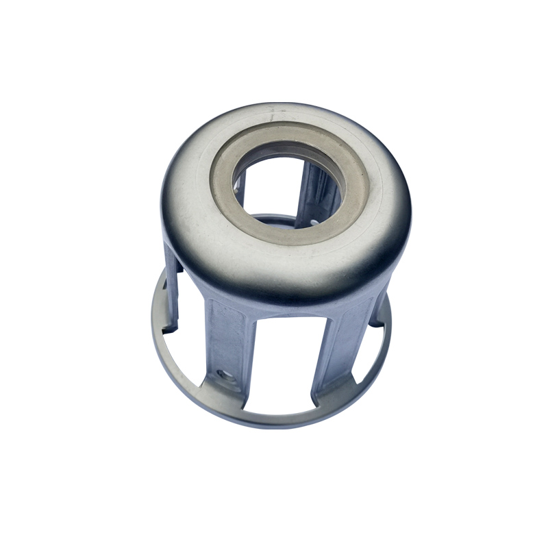
Cylindrical Aluminum Die Cast Locating Base
A Huabo manufacturing example for sensors, actuators and industrial positioning equipment, combining a cylindrical locating feature integrated into a stable mounting flange. The quotation and control plan are developed from the customer drawing, with special attention to locating diameter, axis-to-base perpendicularity, flange flatness and bolt-pattern location.
 Aluminum alloy; grade confirmed from drawing
Manufacturing basis
Review the component geometry before defining tooling and process controls.
Huabo engineering evaluates functional surfaces, datum relationships, wall transitions, machining stock, finish zones and inspection access against the current 3D model and controlled 2D drawing. The photographed component provides a relevant production reference; the customer specification defines the dimensions, tolerances and performance requirements.
| Review area | Comparable Huabo experience | Current project input |
|---|---|---|
| Comparable component | Huabo manufacturing reference #216 and the photographed production example | Controlled drawing revision and current sourcing requirements |
| Observed geometry | A cylindrical locating feature integrated into a stable mounting flange | Envelope, wall thickness, weight and all controlled dimensions |
| Application context | Sensors, actuators and industrial positioning equipment | Actual assembly, loads, exposure and regulatory requirements |
| Material basis | Aluminum alloy; grade confirmed from drawing | Customer material standard, certificate and approved alternatives |
| Manufacturing route | DFM, tooling, high-pressure die casting, trimming and secondary operations | Machine, tool and fixture selection, annual volume and validation package |
| Critical characteristics | Locating diameter, axis-to-base perpendicularity, flange flatness and bolt-pattern location | Numeric tolerances, test method, sampling level and report format |
Part-specific engineering control
The control plan starts from the component’s functional relationships.
For this cylindrical aluminum die cast locating base, the photographed geometry and recorded application point to the control areas below. Numeric limits remain governed by the current customer drawing and purchase specification.
| Control area | Manufacturing concern | Evidence or input to define |
|---|---|---|
| Functional datum | The production route must start from how the part locates in the final assembly. | Controlled drawing datums, mating features and inspection setup |
| Casting geometry | Wall transitions, ribs, bosses and parting affect filling and ejection. | 3D model, wall/draft review and restricted gate/ejector zones |
| Secondary operations | Machining and finishing can change final relationships and appearance. | Machining stock, setup sequence, finish specification and masking |
| Critical quality characteristics | The generic product name cannot define acceptance. | Customer CTQ list, tolerance, test method and sampling plan |
| Production release | Repeat supply follows the approved evidence package. | Material record, first-piece report, approved sample and revision control |
To resolve the most relevant design and sourcing decisions, continue with how to prepare a complete die casting RFQ, die casting tooling and DFM review, and Huabo quality and dimensional inspection.
Component assessment
Engineering priorities for this geometry and application.
The observations below identify the relationships that should be closed during DFM, quotation and sample approval. Numeric limits remain governed by the controlled drawing and purchase specification.
Part-specific engineering review
Geometry and functional interfaces
This locating base uses a cylindrical reference rising from a stable flange. The cylinder axis must relate correctly to the mounting plane and bolt pattern, and that datum relationship should be reproduced in the machining fixture and CMM setup.
Mounting function to confirm
Sensors, actuators and industrial positioning equipment. Loads, mating surfaces, adjustment direction and the features that locate the assembly should be marked on the drawing. The part name alone does not reveal whether a bore, plane, slot or bolt pattern is the primary functional reference.
DFM focus for the structural path
A cylindrical locating feature integrated into a stable mounting flange. Ribs and bosses are reviewed as a load and metal-flow system rather than isolated features. The tool and fixture concepts should avoid forcing flexible areas, protect locating surfaces and leave practical access for any bore, face, slot or thread machining.
Release evidence that answers the risk
Locating diameter, axis-to-base perpendicularity, flange flatness and bolt-pattern location. First-piece reporting should reproduce the functional datum setup and record the geometric relationships that affect fit. Load, pull-out, torque or assembly validation is added when the customer supplies a defined condition and acceptance level.
Component manufacturing profile
- Part geometry
- A cylindrical locating feature integrated into a stable mounting flange
- Application context
- Sensors, actuators and industrial positioning equipment
- Critical controls
- Locating diameter, axis-to-base perpendicularity, flange flatness and bolt-pattern location
- Supply basis
- Made to customer drawing and approved sample
- Huabo reference
- #216
Controlled production route
From drawing review to repeat shipment.
The exact route is confirmed only after alloy, volume, tolerance, finish, validation and packaging requirements are known.
- Drawing and DFM reviewConfirm revision, wall transitions, draft, parting, slides, projected area, machining stock, CTQs and annual demand.
- Tooling and trialBuild the agreed die route, record trial conditions and correct filling, distortion, trimming or appearance issues before sample approval.
- Casting and secondary operationsDFM, tooling, high-pressure die casting, trimming and secondary operations. Fixtures reference agreed datums, while sealing, thermal, cosmetic and machined surfaces receive the required protection.
- Inspection and production releaseVerify locating diameter, axis-to-base perpendicularity, flange flatness and bolt-pattern location. Link the material record, first-piece results, approved sample and any functional test to the controlled revision.
- Repeat shipmentMaintain traceability, monitor agreed characteristics and package the component to protect machined, threaded, sealing and visible surfaces.
Review the supporting factory evidence for IATF 16949 certification and quality evidence and dimensional and material inspection resources.
RFQ and validation package
Information needed for an accurate, comparable quotation.
Send a STEP or native 3D model together with a controlled 2D drawing. State the material specification, prototype and annual quantities, critical dimensions and datums, surface finish, assembly function, test conditions, documentation and packaging requirements.
For this component, mark the features connected to locating diameter, axis-to-base perpendicularity, flange flatness and bolt-pattern location. If sealing, bearing, thermal, threaded, load-bearing or cosmetic performance is involved, name the test method, acceptance criteria and sampling level instead of relying on a general “high quality” note.
A complete RFQ lets tooling, casting, machining, finishing and inspection be quoted as one traceable scope. Any assumption or exclusion should appear in the quotation before commercial comparison or tool authorization.
Related production examples
Compare adjacent geometries before submitting the RFQ.
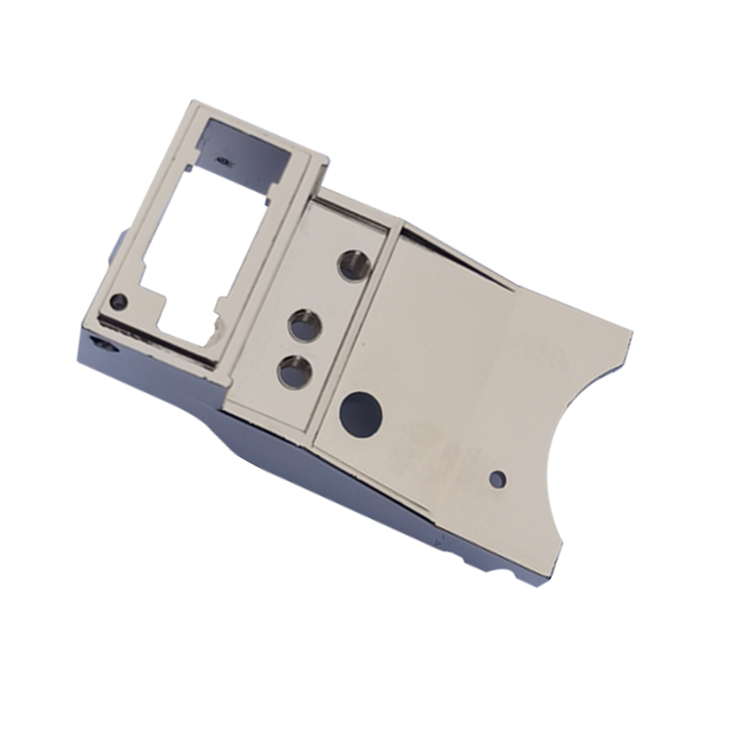
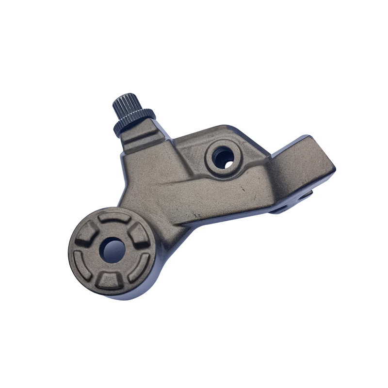
Each component has its own application, geometry, manufacturing route and control priorities. Select the closest example, then send the current drawing for an independent DFM and quotation review.
Request a quotation for this type of component.
Reference “Cylindrical Aluminum Die Cast Locating Base” and attach your drawing, annual demand, finish and quality requirements.