
Quick answer
Porosity control starts by defining the product consequence: leakage, fatigue, thread failure, coating appearance or pore exposure after machining. Mark the critical zone, coordinate geometry and tool-flow decisions, control the process window and use a test method with a measurable acceptance limit. A blanket “no porosity” note is not an inspection plan.
- Buyer decision
- Which porosity risk needs control?
- Use this when
- Parts leak, are machined or carry cyclic load
- Expected output
- Critical-zone and validation specification
Understand gas porosity, shrinkage porosity, machining exposure and the drawing and process decisions used to reduce leakage and strength risk.
Terms used in this guide
For this casting defect prevention, the following terms keep drawing, quotation and supplier-review language consistent. The controlled project specification remains authoritative.
Gas porosity
Voids associated with trapped air, gas or process conditions during filling.
Shrinkage porosity
Voids associated with local solidification and insufficient feeding of a thermal mass.
Critical zone
A defined region where a pore can create a functional or appearance failure.
Functional test
A controlled test—such as leakage—whose conditions and limit represent the product requirement.
Decision summary
The decisions below establish the technical basis for casting defect prevention before price or lead time is compared.
| Decision | What to define | Why it matters |
|---|---|---|
| First decision | Define the failure mode | Leakage, fatigue, thread, cosmetic and machining risks differ |
| Drawing method | Critical-zone map | More useful than an undefined “no porosity” note |
| Process method | Prevent + monitor | Tool design and a stable shot/thermal window work together |
| Acceptance method | Functional evidence | Test conditions and limits must be stated |
Define why porosity matters
Porosity is not one universal acceptance question. A cosmetic cover, structural bracket, machined bearing housing and pressure-containing part have different risk. First define whether the concern is leakage, fatigue, thread integrity, coating appearance or exposure after machining.
Mark critical zones on the drawing and provide a functional test where possible. A blanket “no porosity” note is difficult to manufacture and inspect without a defined method.
Control the sources
Gas can enter through trapped air, poor venting, lubricant or turbulent filling. Shrinkage is connected to local thermal mass, solidification and feeding. Wall transitions, isolated thick bosses and poorly balanced flow paths deserve review before tool release.
Gate and overflow design, venting, shot profile, metal temperature, die temperature, spray control and cycle stability work together. Process changes should be evaluated against the approved part and documented control limits.
Plan machining and verification
Machining can expose subsurface pores. Critical sealing or bearing surfaces therefore need coordinated casting location, machining stock and inspection. Leakage tests, radiography, sectioning or density methods may be relevant depending on the part.
State the test medium, pressure, hold time, permissible leakage, sample frequency and required record. Match the verification method to the failure mode rather than adding tests without a decision rule.
Apply this engineering decision through Quality inspection and Gearbox housing example.
Technical deep dive
Move from a pore image to a functional control plan
Porosity data becomes useful only when location, mechanism, downstream exposure and product consequence are connected.
Define the zone and consequence
Overlay sealing paths, bearing seats, threads, high-stress sections and machining depth on the casting review. Noncritical pores should not automatically be judged by the same rule.
State whether the risk is leakage, fatigue, appearance, coating blister, torque failure or dimensional instability. That choice determines the suitable evidence and sampling.
Distinguish containment from process correction
Leak testing or radiography can contain suspect output, but they do not by themselves correct turbulent filling, poor venting, thermal imbalance or unstable spray.
Use defect location and section morphology with shot, temperature and cycle records. Confirm changes one cause group at a time so the new process window is understood and repeatable.
Control the machining and finishing handoff
Mark how much stock will be removed and where a newly exposed pore becomes unacceptable. Review roughing, finishing and cleaning before defining a casting-only limit.
If the part is painted, powder coated or heat treated, validate representative castings through the complete thermal route; subsurface gas can create a different failure after cure.
Evidence to request and retain
| Evidence group | Minimum useful record |
|---|---|
| Risk map | Critical zones and downstream stock removal |
| Process trace | Metal, die, shot, spray and cycle parameters |
| Detection | Method matched to location and failure mode |
| Validation | Machined/finished part tested to measurable limit |
Match the defect mechanism to the control
The same inspection method does not answer every porosity question.
| Observed risk | Likely contributors | Useful control or evidence |
|---|---|---|
| Leak after machining | Subsurface pore opened at a sealing path | Machining-depth overlay plus defined leak test |
| Blister after coating | Trapped gas, contamination or cure exposure | Substrate control and representative coating trial |
| Weak thread or boss | Local pore at high-stress feature | Geometry review, sectioning or load/torque validation |
| Visible surface pits | Skin damage, opened pore or finishing route | Appearance zone and approved repair standard |
| Random lot variation | Unstable metal, die, spray or shot conditions | Process-window monitoring and traceable reaction plan |
Failure modes and controls
For casting defect prevention, each risk below is tied to a cause, product consequence and measurable prevention or validation control.
| Risk | Typical cause | Possible consequence | Recommended control |
|---|---|---|---|
| Gas entrapment | Turbulent flow, trapped air or spray residue | Rounded pores and leakage paths | Improve filling pattern, vents/overflows and process control |
| Shrinkage porosity | Isolated thick mass and poor solidification balance | Irregular cavities in bosses or transitions | Core out mass, smooth wall transitions and rebalance thermal conditions |
| Machining breakout | Critical surface intersects a porous zone | Open pores on seal, bore or thread | Coordinate gate/overflow design, stock and machined zone |
| Acid or coating bleed | Porosity retains processing chemistry | Staining, blistering or delayed finish defect | Validate pretreatment and consider impregnation only when specified and approved |
| False inspection security | One test method is applied to every risk | Defect escapes or unnecessary cost | Choose leakage, radiography, sectioning or other methods by failure mode |
Recommended engineering workflow
Apply this sequence to the casting defect prevention and record unresolved assumptions at every gate so later operations do not optimize against different requirements.
- 01Classify the functional consequence of porosity
- 02Mark critical zones and machining depth
- 03Review part geometry, gate, overflow and vent locations
- 04Establish metal, die, shot and spray control windows
- 05Validate with representative machining and finish
- 06Approve a measurable test method, frequency and limit
Buyer and engineering guidance
A practical containment and root-cause sequence
First protect the customer: identify affected lots, inspect the functional characteristic and segregate suspect material. Do not change several process variables before the failure signature is understood.
Compare pore location with gate, overflow, vent, wall transition and machining depth. Location is usually more diagnostic than a single overall porosity percentage.
After correction, confirm effectiveness on the real downstream route. A casting that looks improved before machining may still expose pores after stock removal or fail after coating heat.
Application example
Example: porosity review for a machined gearbox housing
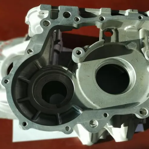
Bearing seats and sealing faces are more sensitive than non-machined exterior ribs. The team should overlay the machined depth and sealing path on the casting-flow review, then decide where process monitoring and additional verification are justified.
A pressure or leakage requirement must state medium, pressure, stabilization, hold time, allowable loss, sample frequency and record retention. A radiographic image without a linked acceptance rule does not by itself prove functional sealing.
Engineering and purchasing checklist
Use this casting defect prevention checklist during design review, quotation and sample approval; add any customer-specific regulatory or functional controls.
- Classify the risk as leakage, fatigue, thread, cosmetic or machining exposure
- Mark critical zones instead of applying an undefined no-porosity note
- Review thick sections, wall transitions, gates, overflows and venting before tool release
- Control metal, die, spray and shot parameters through an agreed process window
- Specify test method, pressure or load, sample frequency and acceptance limit
Frequently asked questions
Can high-pressure die casting be completely pore-free?
Absolute pore-free claims are not a practical general specification. Define the functional risk and a measurable acceptance method.
Why do pores appear after CNC machining?
Subsurface gas or shrinkage pores can be opened when stock is removed, so casting location and machining allowance must be coordinated.
Is radiography required for every part?
No. Inspection should match the risk. Leakage testing, sectioning, density, radiography or process control may be appropriate for different components.
Standards and technical references
For this casting defect prevention, use the current contract edition of each source. These references support review terminology but never replace the controlled drawing or written supplier agreement.
Technical review and revision record
- Technical reviewer
- Huabo Technical Team
- Content owner
- Cixi Huabo Machinery Co., Ltd.
- Engineering basis
- Huabo manufacturing experience, current capability evidence, cited standards and drawing-based production practice
- Reviewed
- 26 August 2026
- Review trigger
- Recheck when equipment, certification, process scope, cited standards or product evidence changes
- Project limitation
- Customer drawings, specifications and written approval records remain the authority for every production commitment
Huabo Technical Team reviews the manufacturing guidance as an organizational technical record. This review does not replace project-specific DFM, customer approval or the controlled drawing for any component.
Drawing-based review
Discuss this requirement with Huabo engineering.
Send the controlled drawing, alloy, annual demand, critical dimensions, finish and validation requirements.