
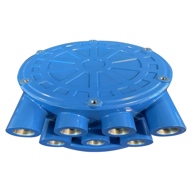
Quick answer
Build the CNC datum plan backward from the assembly. Identify the bore, face and hole relationships that control function, then choose stable as-cast contacts for the first operation and a controlled transfer to final machined datums. Inspect the unclamped part in the same functional reference frame.
- Buyer decision
- Will the machining route preserve assembly relationships?
- Use this when
- Housings contain bores, seals and patterns
- Expected output
- Setup, datum-transfer and inspection logic
Plan as-cast locating points, machined datums, fixture sequence and inspection so bores, faces and hole patterns remain stable in repeat production.
Terms used in this guide
For this machining datum strategy, the following terms keep drawing, quotation and supplier-review language consistent. The controlled project specification remains authoritative.
Datum reference frame
The ordered datum system used to orient the part for geometric tolerancing.
Temporary cast datum
An as-cast locating feature used to establish the first machined reference.
Datum transfer
The controlled handoff from one locating scheme or setup to the next.
Free-state inspection
Measurement after the part is released from clamping forces that may distort it.
Decision summary
The decisions below establish the technical basis for machining datum strategy before price or lead time is compared.
| Decision | What to define | Why it matters |
|---|---|---|
| Datum purpose | Represent assembly location | Convenient fixture surfaces are not automatically functional datums |
| First setup | Establish stable references | As-cast contacts must tolerate normal casting variation |
| Later setups | Preserve relationships | Bores, faces and patterns need controlled datum transfer |
| Inspection | Recreate function | Measure from the same relationships that matter in assembly |
Begin with the assembly datum scheme
The drawing datums should describe how the part functions in the assembly. Machining fixtures and inspection should reference those relationships whenever practical. Selecting convenient but unrelated cast surfaces can create acceptable individual dimensions but poor assembly fit.
Identify bearing bores, sealing faces, mounting planes and hole patterns that must relate to one another. Then choose stable as-cast locating areas and clamping directions that do not distort thin walls.

Coordinate casting allowance and sequence
Machining stock must cover normal casting variation without leaving unnecessary material. Too little stock risks unclean surfaces; too much increases time, heat, tool load and the chance of opening porosity.
Sequence rough and finish operations around part stiffness. If multiple setups are required, define how datums transfer and which feature establishes the final coordinate system.
Make inspection reproduce the functional setup
First-piece measurement should verify the datum strategy before batch release. In-process checks should monitor features most sensitive to tool wear, fixture contamination or casting variation.
For bores and faces, define size, position, runout, flatness or perpendicularity as needed by function. Avoid redundant controls that describe the same relationship in conflicting ways.
Apply this engineering decision through CNC machining capability and Machined ADC12 products.
Technical deep dive
Design the setup chain before cutting the first part
The fixture strategy must accommodate normal casting variation while preserving the final assembly datum relationships.
Choose stable first-operation contacts
Temporary cast locators need adequate area, repeatable draft condition and protection from parting flash, ejector marks and local distortion. Three-point primary support is often preferable to over-constraining an irregular casting.
Mark the intended locator pads during DFM so the tool, trim and machining teams protect them. Verify that clamping does not force a flexible housing into a shape it cannot retain.
Plan stock and operation sequence together
Machining allowance must clean the required surface across expected casting variation without adding unnecessary cutting heat or exposing deeper pores.
Roughing may release residual stress. For sensitive faces or bores, leave controlled finish stock, allow an appropriate sequence and verify the free-state result after unclamping.
Qualify the transfer and measurement frame
When more than one setup is required, define the features that carry the coordinate system forward and how those features are verified.
The CMM alignment should use the controlled datum reference frame. A report built from best-fit alignment can make a poor functional relationship look acceptable unless the drawing specifically permits it.
Evidence to request and retain
| Evidence group | Minimum useful record |
|---|---|
| Fixture concept | Locators, clamps, supports and cut directions |
| Operation drawing | Feature, stock and datum by setup |
| Transfer check | Qualified references between operations |
| Inspection program | Drawing-aligned measurement in free state |
Feature relationship, setup choice and inspection response
Treat each setup as part of one coordinate strategy rather than a separate machining operation.
| Feature group | Machining concern | Control approach |
|---|---|---|
| Bearing bores | Center distance and coaxiality | Coordinate related bores from a common functional frame |
| Seal face | Flatness, finish and opened porosity | Control support, stock and face validation |
| Bolt pattern | Position to bore/face system | Drill from approved datums, not convenient cast edges |
| Thin walls | Clamp distortion and spring-back | Support near cutting load and verify free state |
| Transferred setup | Stacked locating error | Qualify transfer features and report the datum chain |
Failure modes and controls
For machining datum strategy, each risk below is tied to a cause, product consequence and measurable prevention or validation control.
| Risk | Typical cause | Possible consequence | Recommended control |
|---|---|---|---|
| Unstable cast locating point | Flash, draft or local distortion contacts the fixture | Part shifts between cycles | Use robust contact pads and keep parting/overflow features away |
| Over-clamping | Thin wall is forced against the fixture | Dimensions change after release | Support close to cutting forces and control clamp sequence |
| Datum-chain growth | Features are finished in unrelated setups | Bore and hole relationships drift | Create machined master datums early and transfer deliberately |
| Excess stock | Large allowance is used to cover uncertainty | Longer cycle, heat and pore exposure | Use capability evidence to set local, functional allowance |
| Inspection mismatch | CMM setup differs from assembly or fixture logic | Reports pass while assembly fails | Align drawing, fixture and measurement datum systems |
Recommended engineering workflow
Apply this sequence to the machining datum strategy and record unresolved assumptions at every gate so later operations do not optimize against different requirements.
- 01Define the assembly datum reference frame
- 02Map as-cast variation and potential fixture contacts
- 03Choose the first-operation locating scheme
- 04Sequence roughing and finishing by stiffness and heat
- 05Define datum transfer between setups
- 06Validate unloaded parts with functional GD&T and assembly checks
Buyer and engineering guidance
Fixture review questions before CNC release
Ask the supplier to show where the part locates, where it is clamped and which surfaces receive cutting load. A fixture image plus an operation drawing is more informative than a machine list.
Check whether flash, draft or normal cast variation can contact a locator. A locator placed on an unstable as-cast surface can shift the entire pattern while individual tool paths remain accurate.
Review inspection in the same frame. If manufacturing locates one way and the CMM program establishes unrelated datums, the report may not diagnose the actual setup error.
Application example
Example: circular end cover with a bearing bore
The central bore, flange face and bolt circle must work as one system. A practical route establishes the flange or other stable reference, machines the bore and related face with controlled transfer, then drills the bolt pattern from the approved datum frame.
Inspection should report the bore size and its position or runout to the relevant datums, not only three independent dimensions. The fixture qualification and first-piece report should demonstrate that unclamping does not change the result.
Engineering and purchasing checklist
Use this machining datum strategy checklist during design review, quotation and sample approval; add any customer-specific regulatory or functional controls.
- Drawing datums reflect how the part locates in the final assembly
- As-cast fixture contacts are stable, accessible and protected from flash
- Machining stock covers casting variation without becoming excessive
- Setup transfers preserve bore, face and hole-pattern relationships
- First-piece and in-process checks reproduce the functional datum scheme
Frequently asked questions
Should CNC fixtures use the drawing datums directly?
Use the functional datum relationships whenever practical; temporary cast datums may be needed to establish the first machined references.
Why can a thin housing move after unclamping?
Clamping force, residual stress, uneven stock and cutting heat can distort flexible walls, so support and sequence must be planned.
How much machining allowance is correct?
Enough to clean the required surface across expected casting variation, but not so much that time, heat or porosity exposure increases unnecessarily.
Standards and technical references
For this machining datum strategy, use the current contract edition of each source. These references support review terminology but never replace the controlled drawing or written supplier agreement.
Technical review and revision record
- Technical reviewer
- Huabo Technical Team
- Content owner
- Cixi Huabo Machinery Co., Ltd.
- Engineering basis
- Huabo manufacturing experience, current capability evidence, cited standards and drawing-based production practice
- Reviewed
- 26 August 2026
- Review trigger
- Recheck when equipment, certification, process scope, cited standards or product evidence changes
- Project limitation
- Customer drawings, specifications and written approval records remain the authority for every production commitment
Huabo Technical Team reviews the manufacturing guidance as an organizational technical record. This review does not replace project-specific DFM, customer approval or the controlled drawing for any component.
Drawing-based review
Discuss this requirement with Huabo engineering.
Send the controlled drawing, alloy, annual demand, critical dimensions, finish and validation requirements.