
Quick answer
Choose a cast, cored-and-tapped or machined thread route from thread direction, tolerance, engagement, annual volume and tooling access. Then control the thread axis to its seating feature, include plating or coating allowance and inspect after the final operation with the agreed gauge and functional test.
- Buyer decision
- How should the thread be produced and verified?
- Use this when
- Buying zinc connectors, fittings or bases
- Expected output
- Thread route, finish allowance and gauge plan
Plan cast or machined threads, plating allowance, gauges, seating surfaces and assembly tests for zinc die cast connectors and fittings.
Terms used in this guide
For this zinc component design guide, the following terms keep drawing, quotation and supplier-review language consistent. The controlled project specification remains authoritative.
As-cast thread
A thread feature formed during casting with appropriate tool movement or geometry.
Cored and tapped
A cast pilot feature followed by a thread-cutting operation.
Engagement length
The axial length over which mating thread flanks carry load.
Go/no-go gauge
A limit gauge used to quickly verify functional thread size at the agreed operation stage.
Decision summary
The decisions below establish the technical basis for zinc component design guide before price or lead time is compared.
| Decision | What to define | Why it matters |
|---|---|---|
| Thread definition | Standard + class + engagement | Nominal diameter alone is insufficient |
| Production route | Cast or machined | Direction, tolerance, volume and tool complexity decide |
| Finish allowance | Before and after coating | Plating changes pitch and crest diameters |
| Functional control | Gauge + relationship | Axis and seating face matter as much as thread size |
Decide how the thread will be produced
Some thread forms can be created with moving tooling features; others are better machined after casting. The decision depends on thread size, direction, length, tolerance, annual volume, tool complexity and the consequence of failure.
Avoid leaving the thread specification as a nominal diameter only. State the standard, pitch, class, engagement length, direction and gauge requirement.

Account for finishing and seating
Plating or coating can reduce internal thread size and increase external thread size. Masking, allowance or post-finish verification must be planned with the finish supplier.
For fittings, the sealing or seating face may control assembly more than the thread alone. Define runout, shoulder geometry and any leak or torque test needed.
Use gauges and functional validation
Go/no-go gauges provide efficient batch control when the gauge standard and calibration responsibility are clear. First-piece dimensional checks should also confirm thread axis and its relationship to the base or seating face.
Huabo’s zinc product group includes male fittings, threaded couplings, long connectors and mounting bases that show different thread and geometry combinations.
Apply this engineering decision through Zinc die casting products and Zinc die casting capability.
Technical deep dive
Control the complete threaded interface after final finishing
Thread form, axis, seating feature, coating and functional assembly determine whether a zinc component works in production.
Select the production route from direction and volume
Tool-formed threads need release or moving-tool access and sufficient production value to justify complexity. Tapped or machined threads add cycle time but can improve flexibility and control.
Compare total cost, tool maintenance and rejection risk. A low piece-price route is not economical if gauge failures or tool corrections interrupt repeat export orders.
Design the boss and surrounding casting
Provide adequate wall support and gradual transitions around the thread boss. Avoid isolated heavy sections that can increase shrinkage or distort the thread/seating relationship.
Review tool access, chip evacuation and burr removal for machined routes. Protect adjacent cosmetic or sealing faces from tool marks and debris.
Gauge in the final functional condition
State gauge standard, class, calibration responsibility and whether inspection occurs before or after plating. The final size-changing step should be represented.
For sealing or torque applications, use the actual or representative mating part and define assembly torque, leakage or retention acceptance rather than relying only on a thread gauge.
Evidence to request and retain
| Evidence group | Minimum useful record |
|---|---|
| Thread callout | Standard, pitch, class, direction and engagement |
| Route review | Cast, tap, machine or insert with tool access |
| Finish plan | Allowance, masking and final gauge stage |
| Functional check | Torque, seating, retention or leakage as required |
Thread production routes and their control points
Thread size alone is not enough to choose the route.
| Route | Best suited to | Critical controls |
|---|---|---|
| Cast thread | Accessible direction, suitable tolerance and high repeat volume | Tool movement, draft/form, flash and gauge strategy |
| Core then tap | Common internal threads with reliable tool access | Pilot location, tap life, chips and burr removal |
| Fully machined | Tighter geometry or low-volume/flexible production | Machining datum, cycle and burr control |
| Insert or assembly | High wear or special load requirement | Retention, torque and material compatibility |
| Post-finish recheck | Any route affected by plating/coating | Final gauge stage and coating thickness |
Failure modes and controls
For zinc component design guide, each risk below is tied to a cause, product consequence and measurable prevention or validation control.
| Risk | Typical cause | Possible consequence | Recommended control |
|---|---|---|---|
| Incomplete specification | Pitch/class/direction is omitted | Supplier chooses an incompatible gauge basis | State the complete standard designation and mating part |
| Weak boss transition | Threaded boss meets a thin wall abruptly | Crack, sink or filling defect | Use appropriate wall transition and local support |
| Coating build-up | Gauge plan ignores plating | Thread fails after finish | Define allowance, masking and final gauge stage |
| Axis error | Thread is measured without datum relation | Fitting binds or seating face leaks | Control thread axis to mounting or seating datum |
| Burr/flash contamination | Trimming or tapping residue remains | Assembly damage or false torque | Define deburring, cleaning and functional inspection |
Recommended engineering workflow
Apply this sequence to the zinc component design guide and record unresolved assumptions at every gate so later operations do not optimize against different requirements.
- 01Identify mating part and thread standard
- 02Choose cast, cored-and-tapped or fully machined route
- 03Design boss, draft, runout and tool access
- 04Plan plating or coating allowance
- 05Define gauge and datum relationship
- 06Validate torque, seating or leak function when applicable
Buyer and engineering guidance
Treat the thread and seating face as one interface
A thread can pass its gauge while a shoulder, taper or sealing face runs out relative to the thread axis. Control the complete mating interface from a common datum.
Define whether gauges are used before or after plating. For functional acceptance, the last size-changing operation normally determines the relevant gauge stage.
If the part seals or carries torque, add an assembly-level test. A dimensional report alone cannot prove the behavior of the mating system.
Application example
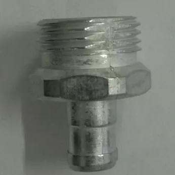
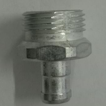
Example: zinc hex male-thread fitting
The thread, hex and seating shoulder must be treated as one interface. Gauge acceptance alone will not catch a shoulder that runs out relative to the thread axis or a coating that changes sealing behavior.
A complete control plan therefore combines thread gauges with shoulder geometry, hex dimensions, coating verification and a representative mating or leak test if the application requires sealing.
Engineering and purchasing checklist
Use this zinc component design guide checklist during design review, quotation and sample approval; add any customer-specific regulatory or functional controls.
- Thread standard, pitch, class, direction and engagement are stated
- Cast versus machined thread route is selected from volume and tolerance
- Plating or coating allowance is included
- Thread axis is controlled to the seating or mounting datum
- Gauge, torque, leak or functional test is defined where needed
Frequently asked questions
Can internal threads be die cast?
Some can be formed with moving tooling, but geometry, direction, tolerance, tool complexity and production volume determine feasibility.
When should a thread be machined?
Machining is considered when tolerance, surface condition, direction or tool complexity makes an as-cast thread unreliable.
Should threads be checked after plating?
Yes when plating affects functional size. The gauge stage and permitted coating build-up should be stated in the control plan.
Standards and technical references
For this zinc component design guide, use the current contract edition of each source. These references support review terminology but never replace the controlled drawing or written supplier agreement.
Technical review and revision record
- Technical reviewer
- Huabo Technical Team
- Content owner
- Cixi Huabo Machinery Co., Ltd.
- Engineering basis
- Huabo manufacturing experience, current capability evidence, cited standards and drawing-based production practice
- Reviewed
- 26 August 2026
- Review trigger
- Recheck when equipment, certification, process scope, cited standards or product evidence changes
- Project limitation
- Customer drawings, specifications and written approval records remain the authority for every production commitment
Huabo Technical Team reviews the manufacturing guidance as an organizational technical record. This review does not replace project-specific DFM, customer approval or the controlled drawing for any component.
Drawing-based review
Discuss this requirement with Huabo engineering.
Send the controlled drawing, alloy, annual demand, critical dimensions, finish and validation requirements.