
Quick answer
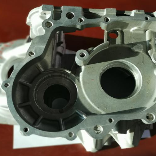
For a die cast gearbox housing, plan casting, CNC machining and inspection around the bearing and shaft reference system. Protect sealing zones from porosity, machine related bores and faces through a controlled setup chain, measure the unclamped part and add leak, rotation or assembly tests when function requires them.
- Buyer decision
- Will bores, faces and seals work as one system?
- Use this when
- Sourcing motor or gearbox housings
- Expected output
- Machining and release evidence by feature group
Control bearing bores, shaft-center distance, sealing faces, hole patterns and porosity exposure in aluminum die cast gearbox housings.
Terms used in this guide
For this powertrain housing guide, the following terms keep drawing, quotation and supplier-review language consistent. The controlled project specification remains authoritative.
Shaft-center distance
The controlled spatial relationship between rotating axes.
Bearing fit
The size and geometry relationship used to locate and retain a bearing.
Sealing land
A face or path whose geometry and surface condition support a gasket or seal.
Cleanliness requirement
A defined limit and verification method for residual chips, particles or contamination.
Decision summary
The decisions below establish the technical basis for powertrain housing guide before price or lead time is compared.
| Decision | What to define | Why it matters |
|---|---|---|
| Functional frame | Bearing bores + shaft centers + faces | Inspect relationships, not isolated sizes |
| Casting input | Porosity and distortion map | Machining stock cannot solve every casting risk |
| Fixture plan | Stiff support + controlled transfer | Avoid clamping flexible walls into tolerance |
| Release evidence | Dimensional + functional | Leak and assembly tests answer different questions |
Identify the functional relationships
A gearbox housing is controlled by relationships between bearing bores, shaft centers, mounting faces and cover or sealing interfaces. The datum scheme should describe those relationships clearly.
Review loads, bearing fits, seal locations, lubrication and alignment requirements before choosing tolerances or a machining sequence.

Plan fixtures and machining setups
Use stable cast locating points and clamp where the housing has sufficient stiffness. Roughing and finishing may need separate stages so cutting stress or heat does not shift the final bore relationship.
Coordinate cover faces, bores and bolt patterns across setups. Define where machining stock is required and protect areas where porosity exposure would affect sealing or bearing support.
Measure what affects assembly
First-piece inspection may require bore size, coaxiality or position, shaft-center distance, face flatness, perpendicularity and hole position. A functional gauge or mating-component check can complement coordinate measurement.
If leakage matters, state test conditions. The catalog includes general aluminum, sandblasted ADC12 and CNC-machined ADC12 gearbox housings for comparison.
Apply this engineering decision through Gearbox and motor industry and CNC machined gearbox housing.
Technical deep dive
Release a housing by functional feature groups
Bearing, shaft, seal, mounting and cleanliness requirements should remain connected from casting design through final inspection.
Protect the bearing and shaft coordinate system
Identify which bores establish shaft position and which faces establish axial location. Control related features from the same datum structure and minimize unnecessary setup transfers.
Review boring sequence, tool reach, support and thermal effects. Measure roundness, cylindricity, position or runout only where function requires them and with the correct datum alignment.
Treat sealing as geometry plus material integrity
A leak path can arise from flatness, roughness, machining marks, damaged edges or opened porosity. Mark the complete path and any gasket compression requirement.
A dimensional result cannot replace a functional leak test when sealing is critical. Define medium, pressure, stabilization, hold, allowable loss and sampling.
Control cleanliness and export protection
Deburr cross-holes, threads and internal passages, then define washing, drying and particle/visual acceptance where contamination can harm bearings or valves.
Cap or wrap sensitive bores and seal faces. Packaging should maintain orientation, prevent corrosion and preserve batch identity through international transport.
Evidence to request and retain
| Evidence group | Minimum useful record |
|---|---|
| Datum map | Bearing, shaft, seal and mounting relationships |
| Machining plan | Setup chain, stock and clamp/support logic |
| Release report | Dimensional plus leak/assembly results |
| Clean pack | Deburr, wash, protection and traceability |
Feature-specific approval plan for a machined housing
Different functional zones need different evidence.
| Feature zone | Primary risk | Release evidence |
|---|---|---|
| Bearing bores | Size, alignment and distortion | CMM/bore results in functional datum frame |
| Seal faces | Flatness, roughness and exposed pore | Surface result plus leak test if required |
| Bolt patterns | Position to bearing/seal frame | True position and mating check |
| Passages/threads | Chips, burrs or blocked flow | Cleanliness and visual/functional check |
| Mounting feet | Rocking or assembly stress | Flatness/profile and representative assembly |
Failure modes and controls
For powertrain housing guide, each risk below is tied to a cause, product consequence and measurable prevention or validation control.
| Risk | Typical cause | Possible consequence | Recommended control |
|---|---|---|---|
| Bore misalignment | Unrelated setups or datum transfer | Bearing load and noise | Machine related bores in a coordinated datum strategy |
| Seal-face leakage | Flatness, roughness or opened porosity | Oil or air leak | Control casting zone, stock, face finish and functional test |
| Housing spring-back | Flexible case is over-clamped | Report changes after unclamping | Support near features and verify in free state |
| Bolt-pattern mismatch | Pattern controlled independently of bore/frame | Assembly interference | Position holes from the functional datum reference frame |
| Cleaning residue | Chips remain in passages or threads | Early field failure | Specify wash, cleanliness and protected packing |
Recommended engineering workflow
Apply this sequence to the powertrain housing guide and record unresolved assumptions at every gate so later operations do not optimize against different requirements.
- 01Define bearing, shaft, seal and mounting relationships
- 02Overlay porosity-sensitive and machined zones
- 03Establish the functional datum frame
- 04Plan coordinated rough/finish machining setups
- 05Measure free-state geometry and surface condition
- 06Run specified leak, rotation or assembly validation
Buyer and engineering guidance
Why a CMM report is necessary but not sufficient
A report can confirm geometric relationships only if its datum alignment matches the drawing and the part is measured in an appropriate state. Ask for the alignment definition, not only a color map.
Leakage, rotation and cleanliness are functional questions. Connect each to stated conditions and an acceptance limit instead of assuming dimensions prove them indirectly.
Review packaging after cleaning. Open bores, seal faces and internal passages need protection from chips, corrosion and contact damage during export handling.
Application example
Example: CNC-machined ADC12 gearbox housing
The machining plan should establish stable references, finish bearing locations and sealing faces from a controlled setup chain, and preserve shaft-center relationships. Broad cosmetic or nonfunctional surfaces should not drive unnecessary precision.
The approval report should identify the exact datum frame, report bore and face characteristics, record the part in an unclamped state and include leakage or mating-component evidence if required by function.
Engineering and purchasing checklist
Use this powertrain housing guide checklist during design review, quotation and sample approval; add any customer-specific regulatory or functional controls.
- Bearing bores and shaft centers share a functional datum strategy
- Cover and sealing faces have defined flatness and surface condition
- Machining setups preserve bore-to-face and bore-to-bore relationships
- Porosity risk is reviewed around sealing and bearing zones
- Leakage or assembly tests include conditions and acceptance limits
Frequently asked questions
Which gearbox dimensions are usually most important?
Bearing fits, shaft-center relationships, sealing faces, cover holes and mounting interfaces usually drive assembly performance.
Why machine bores in a coordinated setup?
A coordinated setup can reduce datum transfer error and improve relationships between bearing locations.
Is a CMM report enough for leakage performance?
No. Dimensional verification and functional leakage testing answer different questions; use both when the drawing risk requires them.
Standards and technical references
For this powertrain housing guide, use the current contract edition of each source. These references support review terminology but never replace the controlled drawing or written supplier agreement.
Technical review and revision record
- Technical reviewer
- Huabo Technical Team
- Content owner
- Cixi Huabo Machinery Co., Ltd.
- Engineering basis
- Huabo manufacturing experience, current capability evidence, cited standards and drawing-based production practice
- Reviewed
- 26 August 2026
- Review trigger
- Recheck when equipment, certification, process scope, cited standards or product evidence changes
- Project limitation
- Customer drawings, specifications and written approval records remain the authority for every production commitment
Huabo Technical Team reviews the manufacturing guidance as an organizational technical record. This review does not replace project-specific DFM, customer approval or the controlled drawing for any component.
Drawing-based review
Discuss this requirement with Huabo engineering.
Send the controlled drawing, alloy, annual demand, critical dimensions, finish and validation requirements.