
Quick answer
A die cast heat sink must satisfy two systems at once: manufacturable metal flow and a controlled thermal path. Review fin direction, thickness, spacing, draft and ejection with the die; separately control the heat-transfer base, interface flatness, machining, masking, airflow and assembly-level thermal validation.
- Buyer decision
- Can the geometry cast and meet thermal duty?
- Use this when
- Designing finned housings or thermal bases
- Expected output
- Manufacturable geometry plus thermal validation
Balance fin filling, thermal-face flatness, alloy, machining, anodizing or coating and inspection for die cast heat sink components.
Terms used in this guide
For this thermal component design, the following terms keep drawing, quotation and supplier-review language consistent. The controlled project specification remains authoritative.
Thermal interface
The contact stack between heat source and casting, including flatness, roughness and interface material.
Fin efficiency
How effectively a fin transfers heat relative to its ideal uniform-temperature performance.
Flow length
The distance liquid metal must travel to fill a feature before solidification.
Natural convection
Air movement created by temperature-driven density differences rather than a fan.
Decision summary
The decisions below establish the technical basis for thermal component design before price or lead time is compared.
| Decision | What to define | Why it matters |
|---|---|---|
| Thermal path | Source → interface → base → fins → air | Fin count alone does not determine performance |
| Castability | Fin ratio + flow direction | Tall, thin, crowded fins raise filling and ejection risk |
| Interface | Flatness + roughness + TIM | Define only the functional contact area |
| Finish | Thermal + corrosion + electrical | Masking and appearance must be designed in |
Design fins for the casting route
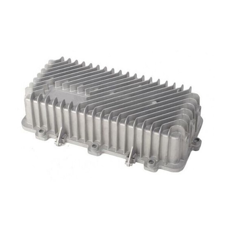
Very thin, tall or closely spaced fins increase filling and ejection risk. Fin direction, draft, tip radius, flow length and local thermal balance should be reviewed with the die layout.
A heat sink is not judged by fin count alone. Base thickness, contact area, airflow and the thermal path through the assembly determine performance.
Control the heat-transfer interface
The mating surface may need machining to achieve flatness and surface condition. Define the contact zone, flatness, roughness and any thermal-interface material instead of applying a tight requirement to the entire casting.
Coordinate machining stock with porosity risk. Mask the heat-transfer face during anodizing or coating if the assembly requires bare metal or a controlled film.
Validate function and handling
Dimensional inspection covers base flatness, hole position and envelope. Thermal testing should reproduce the actual heat input, airflow and mounting condition if it is required for approval.
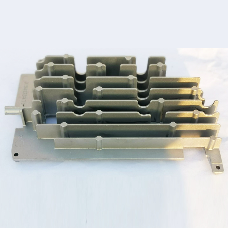
Protect fins during trimming, finishing, transport and packing. Huabo has produced spiral, straight-finned, machined ADC12, black-anodized and A380 heat sink components.
Apply this engineering decision through Heat sink products and A380 heat sink example.
Technical deep dive
Balance metal flow, thermal path and assembly constraints
The best-performing virtual heat sink is not useful if its fins cannot fill, eject, survive handling or contact the heat source correctly.
Design fins for filling and ejection
Review fin thickness-to-height ratio, spacing, draft, root radius, flow direction and tip condition with the actual die concept. Long thin features near the end of fill need particular attention.
Add nonfunctional handling and ejection areas where possible. Ejector force, trimming, blasting and packaging should not rely on fragile fin tips.
Control the base and heat-source interface
Define the actual heat-source footprint, interface material, mounting points, torque, flatness and roughness. A thick base can spread heat but also adds casting thermal mass and weight.
Machine only the functional footprint when practical. Coordinate stock with porosity risk and mask the interface during anodizing or coating if the final system requires bare contact.
Validate in representative airflow and orientation
Natural convection depends strongly on orientation and spacing around the fins. Forced-air performance depends on fan curve, ducting and recirculation.
Run the test in the intended enclosure with neighboring components or a justified equivalent setup. Record heat input, ambient, airflow, mounting and stabilized temperatures so results can be reproduced.
Evidence to request and retain
| Evidence group | Minimum useful record |
|---|---|
| Thermal inputs | Heat load, limits, ambient and airflow |
| DFM review | Fin/base geometry, tool flow and ejection |
| Interface control | Footprint, stock, flatness, roughness and mask |
| System test | Mounted assembly at representative conditions |
Thermal requirement, casting decision and validation
Do not optimize a fin dimension without checking the complete heat path.
| Design input | Manufacturing response | Validation |
|---|---|---|
| Heat load and temperature limit | Select base/fin geometry and alloy basis | Instrumented thermal test |
| Airflow and orientation | Set fin direction, spacing and obstruction clearance | Test in representative enclosure/orientation |
| Interface footprint | Plan base thickness and machining stock | Flatness, roughness and mounted temperature |
| Finish and masking | Protect contact, grounding and thread zones | Coating/masking inspection |
| Handling | Provide non-fin locating and packing contacts | Post-shipment dimensional/visual check |

Failure modes and controls
For thermal component design, each risk below is tied to a cause, product consequence and measurable prevention or validation control.
| Risk | Typical cause | Possible consequence | Recommended control |
|---|---|---|---|
| Incomplete fins | Long flow, thin tips or trapped air | Reduced area and cosmetic rejects | Review fin direction, draft, tip radius, gate and vent route |
| Base distortion | Uneven mass and cooling | Poor thermal contact after assembly | Balance thickness and define local machining/flatness |
| Interface over-tolerance | Whole casting receives precision flatness | Unnecessary machining and cost | Limit the requirement to the true heat-transfer footprint |
| Finish blocks function | Coating covers thermal or ground pads | Higher resistance or electrical failure | Mask and verify functional surfaces |
| Handling damage | Thin fins carry fixture or packaging loads | Bent fins and reduced airflow | Design handling points and protective packaging |
Recommended engineering workflow
Apply this sequence to the thermal component design and record unresolved assumptions at every gate so later operations do not optimize against different requirements.
- 01Define heat source, maximum temperatures and ambient
- 02Model conduction path and airflow boundary conditions
- 03Set manufacturable fin and base geometry
- 04Review alloy, tool filling and ejection
- 05Define interface machining and finish masking
- 06Validate the complete mounted assembly under representative heat and airflow
Buyer and engineering guidance
What thermal simulation often leaves out
Simulation inputs should include the actual interface material, contact pressure, mounting torque, airflow obstruction and heat-source footprint. Ideal contact assumptions can hide a poor machined base.
Casting variation matters at the thin features and broad base. A geometry that fills at trial conditions must remain stable across the approved process window without bent fins or excessive base distortion.
Validate the mounted assembly, not only a loose heat sink. Orientation, neighboring components and enclosure recirculation can dominate the result.
Application example
Example: A380 finned heat sink base
A broad base with multiple fins may cast well but still perform poorly if the mating surface is not controlled or airflow is blocked in the final enclosure. Thermal simulation assumptions should be checked against the real mounting and orientation.
Approval should combine dimensional checks on the contact footprint and mounting holes with a thermal test using the intended interface material, torque, heat load and airflow. Packaging must protect the fins without touching the machined base.
Engineering and purchasing checklist
Use this thermal component design checklist during design review, quotation and sample approval; add any customer-specific regulatory or functional controls.
- Fin thickness, height, spacing and direction suit filling and ejection
- Base thickness and thermal path match the real heat source
- Heat-transfer face has defined flatness, roughness and machining scope
- Coating or anodizing includes masking of functional interfaces
- Thermal validation reproduces mounting, airflow and heat input
Frequently asked questions
Are more fins always better?
No. Fin efficiency depends on spacing, airflow, base conduction and the complete thermal path; fins must also be manufacturable.
Should the heat-transfer face be machined?
Machining may be needed for flatness and contact, but the requirement should come from the interface and thermal analysis.
How should fins be protected?
Trimming, blasting, racking, transport and packaging should support the part without bending or rubbing the thin features.
Standards and technical references
For this thermal component design, use the current contract edition of each source. These references support review terminology but never replace the controlled drawing or written supplier agreement.
Technical review and revision record
- Technical reviewer
- Huabo Technical Team
- Content owner
- Cixi Huabo Machinery Co., Ltd.
- Engineering basis
- Huabo manufacturing experience, current capability evidence, cited standards and drawing-based production practice
- Reviewed
- 26 August 2026
- Review trigger
- Recheck when equipment, certification, process scope, cited standards or product evidence changes
- Project limitation
- Customer drawings, specifications and written approval records remain the authority for every production commitment
Huabo Technical Team reviews the manufacturing guidance as an organizational technical record. This review does not replace project-specific DFM, customer approval or the controlled drawing for any component.
Drawing-based review
Discuss this requirement with Huabo engineering.
Send the controlled drawing, alloy, annual demand, critical dimensions, finish and validation requirements.